Initial Prototype: Demonstration and explanation of Pre-Switch AI during initial power up and first learn
CleanWave200 evaluation system, 600V DC input, 2000 microseconds continuous running,10kHz Fsw, 3 parallel SiC MOSFETs per switch location. PWM input is varied to produce a ramp to simulate the first part of a sine wave output.
The following is a series of 20 single microsecond transition screen captures over a 2000 microsecond period of continuous operation of the CleanWave200 evaluation system. The GIF files illustrates the Pre-Switch AI actively learning at initial start up with unknown starting conditions and ultimately optimizing timing and subsequent adjustments necessary to ensure that a PWM input generates a current ramp to simulate the first part of a sine wave output.
Explanation of switching cycles:
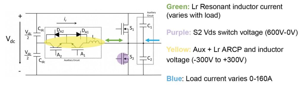
Switching cycle 0: Upon the first switching cycle (corresponding when the “T” in the top preview screen is on the far left side), the Pre-Switch AI controller assesses multiple inputs and decides what mode the system is in and then makes a safe but unoptimized estimate of the resonant period needed for soft switching. In general, the Pre-Switch AI decides to issue an auxiliary resonant switch timing that results in a larger than needed resonant period and thus a large resonant current into and out of the resonant inductor (Green) well in excess of the load current. This is done to ensure that for the first switching cycle, sufficient current is injected into the resonant circuit to ensure that the power switches are soft-switched. This soft-switching is not fully optimized and the excessive current into and out of the inductor causes non-optimal current which causes excess losses in the main switch body diodes. All inputs and outputs are measured precisely and stored for future learning. The AI will finely optimize the full system after another learning cycle is completed.
Switching cycle 1: In this switching cycle, all AI inputs and resulting outputs from switching cycle 0 again measured precisely and analyzed. The AI again issues a second conservative resonant timing period similar to switching cycle 0 to ensure safe but non optimized soft-switching.
Switching cycle 2: The AI algorithm is now quantitatively confident and predicts the optimized resonant timing to ensure full soft-switching with minimized losses in all aspects of the system. The engineer will note the large adjustment in the resonant current period (Green) on switching cycle 2. Inputs from this switching cycle and previous system dynamics are stored for more precise predicted soft-switching and a more intelligent understanding of the power system.
Switching cycle 3: The AI compares system inputs and results from previous switching cycles and adjusts the resonant timing to fully optimize soft-switching with the increasing load current (blue). These inputs and outputs are added to previous switching cycle inputs and resulting resonant timings to improve accuracy in the desired system optimization.
Switching cycle 4-19: Note varying inductor resonant current (Green) with load current (light blue) and switch dV/dt/. Switch overshoot (purple) is reduced. Results continue to be stored to maintain accurate system timing. Changes in system temperature, device degradation and abrupt current swings are all accounted for and optimized within the Pre-Switch AI algorithm.